Posts

Showing posts from January, 2013

OSPF–Point To Multipoint Non-Broadcast

Image
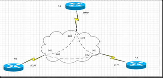
Using same setup that we have been using in the last 3 posts, we will change the network type to point-to-multipoint Non-Broadcast we will also add a Ethernet link between R2 and R3 and enable OSPF on it Our final configuration should be something like this R1 interface Serial0/0   no ip address   encapsulation frame-relay   no frame-relay inverse-arp ! interface Serial0/0.123 multipoint   ip address 10.1.123.1 255.255.255.0   ip ospf network point-to-multipoint non-broadcast   ip ospf 1 area 0   frame-relay map ip 10.1.123.2 102   frame-relay map ip 10.1.123.3 103 !          router ospf 1   router-id 1.1.1.1   log-adjacency-changes   neighbor 10.1.123.2   neighbor 10.1.123.3 R2 interface Serial0/0   no ip address   encapsulation frame-relay   no frame-relay inverse-arp ! interface Serial0/0.123 multipoint   ip address 10.1.123.2 255.255.255.0   ip ospf network point-to-multipoint non-broadcast   ip ospf 1 area 0   frame-relay map ip 10.1.123.1 201 R3 interface

OSPF–Point To Multipoint Networks

Image
using the same setup we used in the last 2 posts for Broadcast and Non-Broadcast Networks, but we will create multipoint interface on each router R1 interface Serial0/0   no ip address   encapsulation frame-relay   no frame-relay inverse-arp ! interface Serial0/0.123 multipoint   ip address 10.1.123.1 255.255.255.0   frame-relay map ip 10.1.123.2 102 broadcast   frame-relay map ip 10.1.123.3 103 broadcast R2 interface Serial0/0   no ip address   encapsulation frame-relay   no frame-relay inverse-arp ! interface Serial0/0.123 multipoint   ip address 10.1.123.2 255.255.255.0   frame-relay map ip 10.1.123.1 201 broadcast R3 interface Serial1/0   no ip address   encapsulation frame-relay   no frame-relay inverse-arp ! interface Serial0/0.123 multipoint   ip address 10.1.123.3 255.255.255.0   frame-relay map ip 10.1.123.1 301 broadcast we will enable OSPF under all sub interfaces interf s0/0.123 ip ospf 1 area 0 R2 interf s0/0.123 ip ospf 1 area 0 R3 interf s1/0.123 ip ospf

OSPF - Broadcast Networks

Image
We are building this lab on the previous lab OSPF – Non Broadcast Networks We will remove the neighbor statements from R1 OSPF process and also changing the OSPF network type under the serial interfaces to Broadcast R1 interface Serial0/0   ip address 10.1.123.1 255.255.255.0   encapsulation frame-relay   ip ospf network broadcast   ip ospf 1 area 0   frame-relay map ip 10.1.123.2 102   frame-relay map ip 10.1.123.3 103   no frame-relay inverse-arp R2 interface Serial0/0   ip address 10.1.123.2 255.255.255.0   encapsulation frame-relay   ip ospf network broadcast   ip ospf priority 0   ip ospf 1 area 0   frame-relay map ip 10.1.123.1 201   frame-relay map ip 10.1.123.3 201   no frame-relay inverse-arp R3 interface Serial1/0   ip address 10.1.123.3 255.255.255.0   encapsulation frame-relay   ip ospf network broadcast   ip ospf priority 0   ip ospf 1 area 0   frame-relay map ip 10.1.123.1 301   frame-relay map ip 10.1.123.2 301   no frame-relay inverse-arp Remember the OSPF netw

OSPF Area Types - Broadcast

Image
In this post and the following posts we will try to explore OSPF network types, OSPF is a core technology in the CCIE lab so you need to be able to configure it without referring to the DoC-CD In Cisco world, OSPF comes in 6 Network types 1- Broadcast 2- Non-Broadcast 3- point-to-multipoint 4- point-to-multipoint Non-Broadcast (Cisco proprietary) 5- Loopback We will examine each of these network types over NBMA (Non Broadcast Multiple Access) Media like frame relay network since this is where the confusion coming from. We will start with the Non-Broadcast networks since it is the default OSPF network when you configure OSPF under frame relay physical interfaces Initial configurations R1 ! interface Serial0/0   ip address 10.1.123.1 255.255.255.0   encapsulation frame-relay   frame-relay map ip 10.1.123.2 102 broadcast   frame-relay map ip 10.1.123.3 103 broadcast   no frame-relay inverse-arp interf lo0 ip add 1.1.1.1 255.255.255.255 R2 ! interface Serial0/0   ip

Private VLANS and protected ports

Image
In this post we will try to learn two layer 2 technologies, private vlans and protected ports Private vlans is used to segregate the layer 2 domain within the same vlan so we don’t waste any IP addresses, think about as sub-vlans within the same vlan that share the same layer 3 address. These sub-vlans can be of two kinds                      1- Community 2- Isolated The difference between community and isolated sub-vlans that hosts within community vlan can communicate together however hosts within isolated vlans con’t communicate to each others, also note that hosts from different community vlans can’t communicate/isolated vlans can’t communicate together. The question is how these hosts in community/isolated vlans communicate to the outside world, and the answer is they communicate through the promiscuous port which is part of parent vlan but this port is allowed to communicate to all sub-vlans whether community or isolated In our setup, we have 2 switches running a trunk port